Adopting a standalone Z-axis sensor through multi-chip packaging is a common method for implementing a tri-axis magnetometer. However, this construction can cause potential failures during high-temperature or reflow processes. iSentek’s unique flux concentrator structure eliminates the standalone Z-axis sensor, preventing these types of failures and guaranteeing stable performance during PCB reflow or temperature cycling processes.
Reliability Issues of Magnetic Sensors
With the widespread adoption of flight control functions in drones, an increasing number of engineers are encountering 3-axis magnetic sensors in their professional or leisure activities. Often referred to as an electronic compass (e-compass), the 3-axis magnetic sensor primarily functions to provide absolute directional pointing, enabling stable drone control and assisting with navigation.
However, when delving into the specifics of 3-axis magnetic sensor components, one will find that internet reviews frequently revolve around certain reliability issues. For example:
Manual soldering is very difficult; slightly higher temperatures can ruin it. Sometimes, even at a soldering temperature of 250°C, it still fails. Complete damage results in an inability to read data, while slight damage manifests as an abnormally small value on a specific axis.
After hot air gun soldering, the self-test mode might show normal X and Z axes, but the Y-axis (the vertical axis) displays extremely small values like -1, 1, or 2; or the Y-axis is normal, but the X and Z axes are very small.
It only supports two to three reflow cycles (front and back). If the board needs repair, it can only undergo a maximum of three reflow reworks.
Poor SMT production yield. During mass production, defect rates of 10% or higher often occur, necessitating rework. However, since the number of allowed rework cycles is limited, a certain amount of scrap is generated.
During outdoor use or testing, magnetic sensor failures occur sporadically, causing the drone body to spin or crash, often without an identifiable cause.
These situations are not isolated to a single supplier’s products; multiple magnetic sensor products experience these phenomena.
The Upright Z-Axis Sensor Structure is the Primary Cause
According to iSentek's research, the reliability issues mentioned above primarily stem from the internal design structure of the magnetic sensors. Most suppliers whose products are prone to these issues use an upright Z-axis sensing chip structure. In other words, 3-axis magnetic sensors with this structure are less resistant to high temperatures, more sensitive to humidity changes, have a limited number of SMT reflow cycles, and, most importantly, are prone to failure when used in outdoor environments with significant temperature fluctuations.
In terms of manufacturing processes, general semiconductor components use a planar process, meaning multiple circuit layers are created on a single plane using lithography. Sensors made with a planar process can detect magnetic field characteristics in two dimensions. However, because a standard planar structure cannot detect the magnetic field in the third dimension (the Z-axis), it cannot fulfill the functions of a 3-axis sensor on its own.
To achieve magnetic field sensing in the third dimension (Z-axis), the common approach is to use multi-chip packaging. Another sensor is placed upright, and solder joints connect its electrical signals to the planar chip. This allows for the detection of magnetic force in the third dimension. In this combination, the planar chip is responsible for the first and second dimensions, while the upright chip handles the third, thereby realizing the function of a 3-axis magnetic sensor.
In the multi-chip packaging process, the aforementioned planar and upright chips must be encapsulated and secured with an epoxy molding compound. When initially manufactured, the relative positions of the chips are fixed in their designated locations. However, as environmental factors (like temperature fluctuations) and time (leading to material degradation) change, the physical positions between the chips can easily shift, generating reliability issues. This explains why, in cases of slight damage, only a single-axis signal becomes smaller, while in severe cases, all three axes are affected.
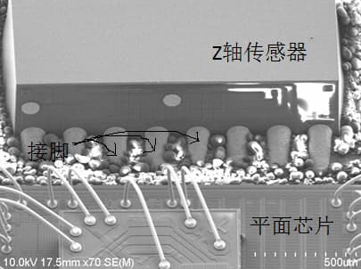
Figure Caption: Enlarged view of a magnetic sensor using multi-chip packaging. The Z-axis sensor at the top is placed upright, and solder joints connect its electrical signals to the planar chip to realize sensing in the third dimension.
However, because the upright Z-axis sensing chip structure is more intuitive and simpler to design, most 3-axis magnetic sensor suppliers in the market adopt this structure.
Analysis of Reliability Issues
How exactly do the reliability issues of the upright Z-axis sensing chip structure occur? The following real-world examples of this structure provide an explanation.
Molding compound squeezed into the upright sensing chip's solder joints: The following image shows that because pressure and heat must be applied when forming the epoxy encapsulation material, some of the molding compound is squeezed into the gaps between the upright sensing chip and the solder joints. When temperature fluctuations are significant, this small amount of material squeezed into the crevices—due to its different expansion and contraction characteristics compared to adjacent materials—can severely affect the signal connection between the upright chip and the planar chip. In mild cases, it reduces the connection area, correspondingly decreasing the electrical signal or increasing resistance; in severe cases, it causes a loss of connection or causes the entire chip to stop functioning.

Figure Caption: Enlarged view of the Z-axis sensor and solder joints. It can be seen that the encapsulation material has been squeezed into the soldering gaps, which can easily lead to failure after subsequent thermal expansion and contraction.
Risk of fracture in the upright chip's circuitry: The following image shows that the circuit layer beneath the solder ball of the upright chip can fracture due to the vertical force applied to the solder ball. The occurrence of such fractures does not necessarily happen during the manufacturing process; they can also occur sporadically due to residual stress. For instance, a fracture might not occur, or might only be slight enough not to affect functionality during manufacturing; but it could manifest after multiple heating cycles during SMT placement, or when used in extreme environments like high or low temperatures. Similarly, if the molding compound deforms significantly during processing due to moisture absorption, it can also indirectly trigger a fracture

Figure Caption: The image above shows that both the upper and lower edges of the solder joints can cause micro-cracks in the Z-axis sensor circuitry.
Risk of delamination of the metal layer beneath the upright chip's solder balls: The upright chip is initially secured via solder balls, which requires downward pressure applied simultaneously with heat. This action generates a peeling force on the metal beneath the solder balls, potentially forming an unstable bonding surface. Again, this delamination might not happen all at once during manufacturing but could occur sporadically due to temperature changes, applied force, or the release of residual stress.
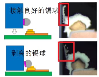
Figure Caption: The image above shows that both the upper and lower edges of the solder joints can cause micro-cracks in the Z-axis sensor circuitry.
iSentek’s Solution
The explanation above details how the practice of using an upright chip structure to achieve Z-axis sensing inherently carries the risk of failure under conditions of temperature change, applied force, or the release of residual stress. To resolve these reliability issues, iSentek’s approach is to integrate the sensing for all three axes onto a planar chip, eliminating the need for an upright chip.
The specific method employs the principle of soft magnetism to redirect the Z-axis magnetic force into a direction that the planar chip can sense. The system then calculates the magnitude of the Z-axis magnetic force through mathematical algorithms.
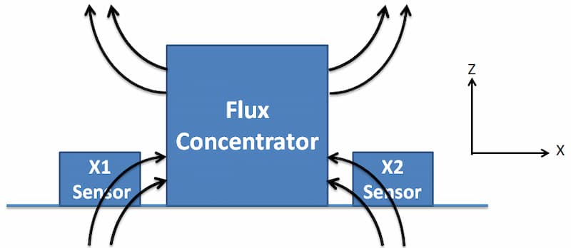
Figure Caption: iSentek's Z-axis sensing design redirects the Z-axis magnetic field lines to the X-axis sensor for detection, realizing 3-axis sensing functionality within a planar structure.
Products using this structure have been verified to have no failure issues after multiple reflows, and their tolerance to environmental temperature changes is completely unaffected. Furthermore, no failures have occurred under various temperature environments or during manual soldering.
About iSentek
Founded in June 2011, iSentek Inc. is a fabless semiconductor design company for mobile sensors, located in New Taipei City, Taiwan. Its core technology lies in the design and sales of MEMS sensor chips. The company also develops related algorithms and provides customer application support to deliver comprehensive and real-time mobile sensor solutions. Its products are used in consumer and industrial electronics, with primary applications including smartphones, navigation devices, drones, virtual/augmented reality (VR/AR) devices, robots, and Internet of Things (IoT) devices. The company's website is www.isentek.com.